Determination of a reliable metrology method to characterize a sphere of confusion in the hundred nanometre range
Introduction
The design of a new diffractometer led us to implement an air bearing as the main rotating platform, capable of rotating at up to 1,000°/s with a sphere of confusion of a few hundred nanometres. To achieve such performance levels, it is necessary to have appropriate metrological equipment to monitor the performance of the rotary table. The required precision determines the metrological procedure to be used. Consequently, our work has focused on establishing a robust procedure applicable when a high-precision rotating stage is involved. Here we present our results for three different methods. We developed two methods using the embedded high resolution viewing device (on-axis camera) in visible light (suitable for everyday use), which we compared with a method based on an external device (interferometer) to obtain the most accurate metrology possible.
What is a sphere of confusion (SoC)
To characterize the performance of the diffractometer, a measurement artefact should be rotated around the Ω axis, and its positional variation in one or more planes of space should be evaluated using a suitable metrology system. The maximum displacement of the artefact observed during its rotation will describe the diameter of the sphere of confusion.
The misalignment of the artefact on the Ω axis is the main factor contributing to its displacement during rotation. By studying this displacement profile, it is possible to calculate the compensations to be applied to the centring axes to cancel out the eccentricity error.
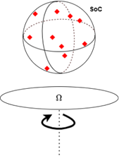
The system’s ability to precisely centre the artefact is then evaluated by the sphere of confusion encompassing all the measured positions of the artefact during rotation. This method can be repeated iteratively, compensating for residual defects until the sphere of confusion is as small as possible, illustrating the diffractometer’s optimal performance. In addition to the eccentricity of the artefact, residual defects can be caused by numerous phenomena that must be eliminated or minimized:
- Friction phenomena,
- Deflection of one or more axes due to poor distribution of loads,
- Deformations caused by mechanical assembly,
- Deformations associated with thermal fluctuations,
- External disturbances, vibrations,
- Insufficiently robust servo systems
SoC evaluation with camera and micropipettes
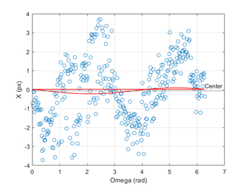
Since the purpose of the on-axis camera is to centre the samples, this method has the advantage of evaluating the diffractometer’s performances under actual operating conditions, but with a resolution limited to the pixel size, which is 72 nm in our case. The measuring device chosen for these tests is a glass micropipette with a tip diameter of 2 µm. The point of interest for the measurement is a virtual point, at the intersection of two lines fitted to the edges of the pipette.
This device is easy to align within the camera’s field of view and can be checked during daily inspections. These image processing tests revealed an intrinsic defect in the device itself, cause by the surface error of the pipette. The surface has an irregular circularity that makes test results non-reproducible from one measurement to the another and from one pipette to another.
SoC evaluation with camera and standard ball
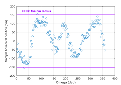
This second approach involves using a standard ball in the field of view of the on-axis camera to eliminate random errors of the metrology monument. An ISO 3290 grade 3 ball with a sphericity of less than 80 nm is set onto the diffractometer centring stages on a sample base. One side edge of the ball is centred by removing the sinusoidal part associated with the sphere’s eccentricity defect. The point of interest is selected as the inflection point of the ball curvature. At each picture frame, this POI is calculated to track its lateral displacement.
The tests results of this method show a lateral displacement of 154 nm radius of the sphere. The repeatability of this measurement has been confirmed over multiple turns on both sample holder and Kappa-Phi head.
SoC evaluation using a laser interferometer
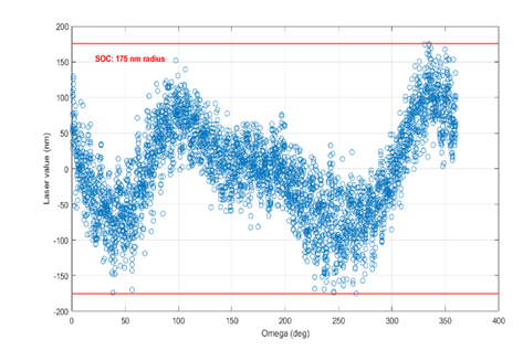
A confirmation measurement of the camera test has been done with a fibre interferometer focused on the surface of a standard high-reflectivity ball with a sphericity of less than 50 nm. This method provides a higher measurement resolution than the camera (100 pm vs 72 nm) and a higher data acquisition rate (1 kHz vs 20 Hz)
Tests confirm the results obtained with the camera : the SOC measures approximately 175 nm in diameter.
The radius of the sphere of confusion is considerably reduced, without any dynamic compensation for the defect being necessary. The radius of the sphere of confusion is systematically less than 200 nm for speed ranges between 10 and 100 degrees/s.
Conclusion
The method of evaluating the SoC using the vision system and standard ball is relevant. It produces results that illustrate the diffractometer’s performance in real-world situations, where only the vision system can be used to centre samples. It also enables 2D performance measurement on the horizontal and vertical axes with easy configuration.
The interferometer method is more complex to implement and cannot be used daily, as it requires a specific setup. It can be however considered for camera confirmation measurements during production or maintenance phases.
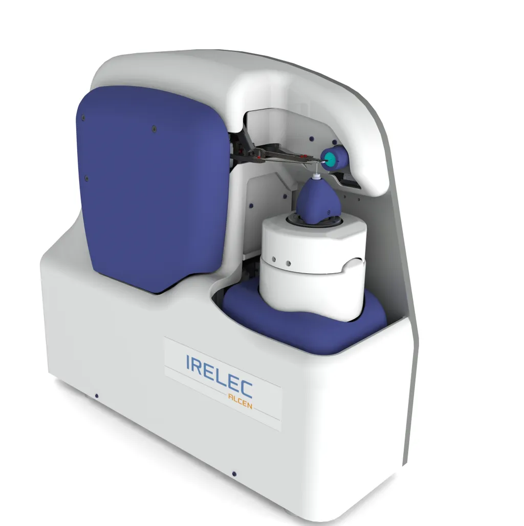
IRELEC new generation single crystal x-ray diffractometer - HiDIFF-X
HiDiff-X unique features make it the ideal companion for modern MX beamlines:
- Performances and StabilityVertical axis-diffractometer with SOC < 200 nm radiusThermal stabilization of the structure and stable mechanical architecture
- High throughput capabilitiesLess than 2s is needed to change configuration (sample loading, alignment, data collection)Fast thermal stabilization of the sample
- Ultimate safety featuresAbsolute encoders on all-axisEmbedded digital twin and Collision Avoidance System
- Fine ErgonomicsFast and secure tool changer for plate holder and Kappa-Phi head integrationAutomatic loop detection and automatic sample centering (raster and omega-scans)
Configurable architecture
And, of course, IRELEC ensures handshake operation with ISARA2 sample changer.
