Synchrotrons: Robotic Sample Handlers Support Advanced Macromolecular Crystallography
Robotic sample handlers are crucial components of crystallography beamlines. From the early automated sample handlers developed in-house to the development of sophisticated robotic sample changers by third-party vendors, these systems are constantly evolving. While reliability is the top performance criterion, maintainability, ergonomics, operability, speed, and autonomy must also be considered when designing or purchasing a sample changer. The best sample changers are also flexible and standards-compliant. And, while cobots—the future of robotics—are not yet 100% relevant to this use case, robotic systems continue to push the boundaries of what is possible on MX beamlines.
Macromolecular crystallography at synchrotrons, a powerful research tool
Synchrotron radiation facilities are home to powerful scientific instruments that serve a variety of disciplines. One synchrotron technique, macromolecular crystallography (MX), is particularly useful in the life sciences.
“Scientists need to understand protein structures because structure determines a protein’s function. Protein structures therefore tell scientists how life works, and, by extension, they also reveal what molecules or drugs are likely to bind with particular proteins in such a way as to combat disease and make people healthier.”
ESRF news – June 2022
The first successful proofs-of-principle of macromolecular crystallography (MX) experiments at synchrotron accelerators were performed in the mid 1970s. Today, 90% of X-ray single-crystal structure determinations are performed with synchrotron radiation (SR).
MX beamline experiments, step by step
The whole process, from crystallization of a macromolecule (a protein, for instance) to determination of the structure, requires many delicate operations.
1 – A solution containing the protein of interest is poured into a so-called crystallization plate.

2 – A complex chemical reaction enables the crystallization of the protein.

3 – The protein crystals are harvested and mounted on a suitable support (sample holder: magnetic base/cap + pin + loop).

4 – The crystals are cryo-cooled to improve storage and protect them from radiation damage during x-ray exposure.

5 – The crystals and their holder are integrated into pucks for transportation to a synchrotron facility.

6 – The crystals are mounted on the synchrotron beamline’s experimental station.

7 – Each crystal is precisely aligned and exposed to the X-ray beam.

8 – Diffraction patterns are recorded using special sensors.

9 – Advanced software determines the protein structure from the diffraction patterns.

A brief history of automation in MX beamline experiments
Instrumentation engineers have been working on ways to automate every step of complex synchrotron experiments since the early days of this type of research. The main goal of automation is to bring the scientific community a high-throughput pipeline.
When crystals arrive at a synchrotron facility, the automation of the whole data collection process (steps 6 to 8) on macromolecular crystallography beamlines is crucial to the efficient use of limited beamtime. Sample-changer robots are key contributors: Samples can be exchanged without entering the experimental hutch, saving scientists a huge amount of time when running experiments.
“Robotic sample mounters have changed the nature of X-ray diffraction data collection, so that automated high-throughput crystallography is no longer fiction. Furthermore, these systems have made remote data collection almost a matter of routine.”
J. W. Pflugrath, Rigaku
Synchrotrons, as well as the experimental techniques used at these facilities, are constantly changing, and their performance, diversity—and sometimes—complexity are increasing. Instruments and automation processes must also be continuously improved to keep pace with these changes, starting with the robotic sample changers.
“Several key boundary conditions have greatly evolved throughout the years, thereby greatly changing the requirements for experimental stations. Beam sizes and average sample sizes shrunk from millimeters to a few microns and data collection times have diminished from days to minutes and now seconds due to the development of faster detectors and brighter X-ray beams. To follow these advances, end station designers had to improve goniometer precision, microscope resolution, incorporate sample automation, and greatly improve the overall stability of the apparatus.”
R.L. Owen et al. / Archives of Biochemistry and Biophysics 602 (2016) 21e31
Robotic sample changers: where they started and where they stand now
The early years of automated sample handling
The first robotic sample changers were developed in-house and implemented in the early 2000s at several synchrotron facilities:
- The SC3 and CATS sample changers at ESRF
- The Stanford Auto-Mounter at SSRL
- The SPACE at Spring-8
The synchrotron community’s interest in advanced robotics has only grown since then, and, even today, beamline instrumentation teams continue to develop sample changers like the BART at DLS, the TELL at SLS, the Flex at ESRF/EMBL, and others.
Robotic sample changers developed by third-party vendors
A number of companies are or have been actively involved in the design and supply of robotic sample changers:
- Rigaku with the Actor, since 2002
- Irelec with the CATS then the ISARA, since 2007
- NatX-Ray with the G-Rob, from 2009 to 2020
Robotic sample changer performance crucial to preserving precious samples
Reliability & maintainability key factors in performance
The integration of automation into tasks and processes traditionally executed manually represents a major change—one that brings new performance expectations. Put simply, robots are expected to do the job more efficiently and with fewer errors than humans.
For a variety of reasons, both subjective and objective, when asked what a robotic system must be able to do, the first answer that springs to mind is “it has to work.”
This is especially true for sample changers at MX beamlines, where major scientific discoveries depend on the success of delicate experiments on samples that are costly and time-consuming to prepare.
Whether it is to prevent sample losses, avoid damaging expensive equipment, or keep experiments running on schedule, downtime at MX beamlines is simply not an option. A robotic sample changer should be highly reliable and easy to maintain in optimal operating conditions.
Classically, the “minimum” reliability expected from a sample changer is the capacity to load/unload 1,000 samples with zero failures.
This high degree of reliability is mainly achieved through:
- Robust, field-proven control software with safety features that prevent users (who are not robotics experts) from performing actions that could damage surrounding equipment.
- A gripper (tool handling the sample bases) with a consistent mechanical design that can handle thermal cycling (77 K « 293 K).
- Well-established (and automated) training and calibration procedures, as well as built-in routines for checking potential drift in system status.
The optimum maintainability of the system is ensured by effective knowledge transfer from the supplier to the user. To limit downtime, the user must be able to resolve most minor issues easily and quickly without depending on the supplier. Detailed documentation, proper training, and involvement of beamline staff throughout the installation and commissioning phases are vital here.
Remote control is also helpful, whether it is to update software or fix bugs or to verify the proper operation of the robot. Downtime can effectively be reduced remotely when no robotics expert is available on site.
Additionally, specific robotic features can improve system maintainability.
- Automatic teaching trajectories that simplify system readjustment after reference points (the goniometer position, for instance) has been modified.
Software features to modify robot trajectories without human intervention. This is useful if the goniometer has several operating positions (different beamline operation modes).
Ergonomics & operability also impact efficiency
Beamline managers and end users are not robotics experts, so a certain amount of apprehension about robotic systems is understandable.
The robotic sample changer must be designed to serve as a companion whose role is to make scientists’ lives easier.
With this objective in mind, the sample changer may, for instance, offer features like:
- An efficient way to track robot operation with comprehensive and detailed log files and alert the beamline contact person in real time in the event of an incident. This can include in-line cameras and a software routine that automatically generates an email alert for specific events.
- Assistance for loading pucks in the Dewar, with an effective puck detection system.
- Automatic recovery procedures for unexpected events.
- Software features to define restricted areas that the robot arm, with its end tool mounted, cannot enter.
And, for any robot, two operating modes are a must.
- Manual, accessible through a teach pendant, used during the trajectory teaching and robotic system commissioning processes.
- Automatic, used remotely during normal operation of the robotic system.
From a practical point of view, the ability to use the teach pendant to enhance functions, such as by enabling it to launch higher level commands to do things like exchanging a sample, is a plus.
Mise en page citation
While sample traceability is not necessarily a major factor in this use case, robotic sample changers can track each stored sample and generate a database of the samples. This database can be connected to the database of experimental data, for example. As both sample holder and pucks can be tagged with 2D barcodes, integrating a barcode reader into the robotic system is a simple way to do this.
Speed & autonomy major performance enablers
Obviously, one of the main reasons for automating sample loading/unloading is to increase experiment throughput by limiting the need for the user to enter the experimental hutch. Today, the minimum sample storage capacity requirement is 25 pucks (about 400 samples).
Ultra-fast detectors are now widely used on MX beamlines, forcing sample changers to complete a transfer in less than 10 seconds. This is possible only with the implementation of twin grippers that can manage two samples simultaneously.
Note that sample transfer time is significantly limited by the time spent exchanging status information with other end-station equipment (diffractometer, cryojet, etc.). So, a comprehensive communication protocol should be set up at the early stage of the automation project to minimize the time required to exchange a sample. The robotic sample changer can offer advanced functionalities to perform time-saving tasks like pre-picking the next sample while data is collected from the previous sample, for instance.
Flexibility & functionality for universal compliance
The strict requirements of automated sample exchangers have driven the development of standardized sample mounts.
In 2005, the Structural Proteomics in Europe (SPINE) project developed a standard sample holder for general use. Standardized containers for the transport of SPINE pins between sites and mounting in sample changers have also been developed, with multiple standards (Unipuck and ESRF/EMBL basket standards, for example) co-existing.
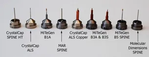
Example of magnetic caps (SSRL style, ALS style and SPINE).
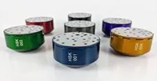
Universal pucks.
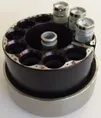
ESRF SC3 pucks.
Today, Universal pucks are rapidly becoming the preferred solution worldwide, as they enable higher sample storage densities and speed up the sample transfer by eliminating vial removal. However, with Unipucks, it is important for the robotic solution chosen to have a compliant gripper that ensures safe sample transfer, avoiding collisions inside the Dewar and keeping the sample temperature sufficiently low during transfer.
By nature, a poly-articulated robot arm is versatile, meaning that it can manage various tasks. On a synchrotron MX beamline, the robotic sample changer can also handle:
- Mounting specific tools into the beam path for alignment or other purposes.
- Mounting crystallization plates onto the diffractometer for in situ
Synchrotron MX beamlines are not homogeneous. Each has its own operating constraints, from available space to supervision software and hardware to be interfaced with. So, the sample changer must be able to adapt, with:
- A scalable robot arm.
- Possible integration of control electronics outside the hutch.
- Flexible/customizable integration of individual components (robot arm, cryogenic Dewar, phase separator, tool rack, etc.).
- Standard low-level communication protocol for easy implementation in any supervision software.
Sample storage at cryogenic temperatures creates specific demands
An MX sample changer is not simply a robotic system, it is a robotic system operating at cryogenic temperatures. The proper management of the LN2 feeding system is the most challenging technical aspect of MX sample changer construction. This system must be considered as a whole if it is to:
- Ensure smooth and automatic Dewar (re-)filling (with controlled flow and pressure).
- Minimize ice formation in the vicinity of the samples.
- Fine tune the LN level inside the Dewar.2
- Control GN2
- Integrate a suitable solution for maintenance (ice accumulation being unavoidable with time, Dewar draining, drying, and refilling should be possible with minimum time and effort).
The cryogenic Dewar and LN2 feeding system are both key sub-assemblies that require precision engineering work and determine the reliable and safe operation of the sample changer.
The shift from robots to cobots: implications for safety
The integration of a robotic system is governed by strict safety regulations and standards intended to guarantee user safety. This is why compliance is so important. In addition, a robotic sample changer can provide functionalities that prevent damage to other equipment on the experimental station:
- By monitoring the power supply to the robot’s various axes to head off collisions before they occur.
- By detecting the presence of samples in various critical locations (inside the gripper, in the Dewar, on the diffractometer).
- By programming restricted zones where the robot arm cannot go, to avoid collisions with other sensitive equipment.
- Unique identification of the tool mounted on the robot arm (if there are multiple tools).
As for many industrial processes, one question is on everyone’s lips these days: Robot or cobot (collaborative robot)? For this kind of use case, on MX beamline end-stations, there is no real need or even the possibility for the user to be in interaction with the robot during data collection. So, the robot vs. cobot question isn’t relevant—at least not yet!
This doesn’t mean that robots with collaborative capabilities aren’t useful:
- During commissioning in nominal conditions.
- If the implementation of a sample changer in an existing end-station is very constrained due to limited space available and/or a “crowded” sample environment. Here, cobots can secure robot trajectories, avoiding any risk of collision.
The final robot vs. cobot decision should consider the performance and features required for the MX sample changer, particularly in terms of speed, repeatability, and durability. For industrial robotic arms, the mean time before failure is very high and their performance has long been known and mastered. The same cannot (yet!) be said for cobots.